IoT in Dynamics 365 Finance & Operations - How It Works
In the previous article we had presented the new D365FO functionality with which we could connect our IoT devices to the ERP and perform 3 types of actions:
- Monitor states and metrics
- Perform actions automatically
- Display notifications for certain events
In today’s article, we will see the tool in action, we will see examples and what result D365FO proposes to us.
As we had already mentioned, there are currently 5 possible scenarios supported by this feature:
- Asset maintenance
- Machine status
- Downtime
- Product quality
- Production delays
For the implementation of the examples we have followed Microsoft’s official documentation and some help from support groups since it is a new functionality and still has a lot to go.
Asset Maintenance
The first scenario we will test will be asset maintenance. In this scenario, imagine that we have a device or machine connected that at a certain operating cycle needs maintenance or needs to have some part changed. The sensor on this device will send us periodically the use that this component is getting, and from here we will see how the ERP reacts.
| Element | Function |
|---|---|
| Sensor | Sends a signal with the number of times an action has been executed |
| Azure | Sends to Redis the aggregate of signals received |
| D365FO | Takes data from Redis and generates a record in asset counters |
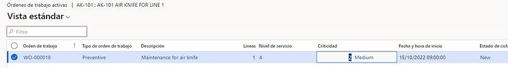
In the asset counter form, the values obtained from the sensor are automatically registered and we see how it accumulates in the aggregate value column.
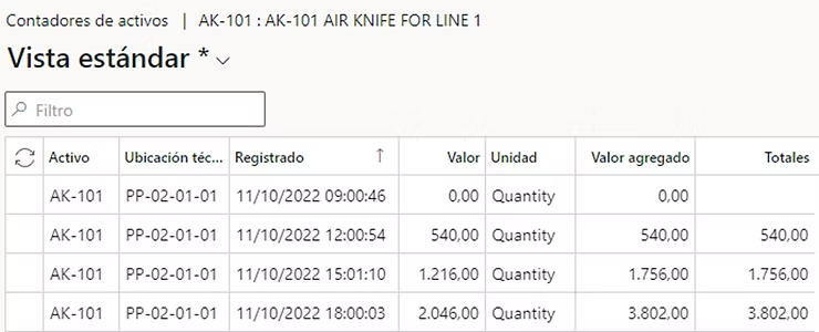
When it reaches the value configured for that asset, a work order is automatically generated to perform maintenance on that component. All this process is done automatically while the sensor sends us the information.
Machine Status
The second scenario to analyze is one that tells us the state of our IoT device. In our example we are going to imagine that we have a device from which we only want to obtain information about whether it is in operation or stopped (e.g.: a conveyor belt, an emergency light…)
| Element | Function |
|---|---|
| Sensor | Sends any signal. Its reception only indicates that the device is in operation. |
| Azure | Sends to Redis the aggregate of signals received |
| D365FO | Takes data from Redis and notifies if the device has undergone a change in its operating state |
As you can see in the following video, the chart shows us the number of signals that Dynamics is receiving regardless of their value. When Dynamics detects that it has not received any signal for 2 minutes (customizable), it sends us a notification to warn us that that device has stopped working.
Once it starts receiving signal again, it warns us in the same way that the device is back in operation.
Downtime
In the next scenario, we will see how downtime of connected devices is measured. This scenario allows analyzing device efficiency by measuring usage time versus inactive time. The principle is the same as in the previous case, we only need the machine to send any signal since we are not interested in its value.
| Element | Function |
|---|---|
| Sensor | Sends any signal. Its reception only indicates that the device is in operation. |
| Azure | It checks if no signal has been received in the threshold set in Dynamics. The result is sent as a notification every minute to Dynamics. |
| D365FO | Generates a record in Downtime by Maintenance |
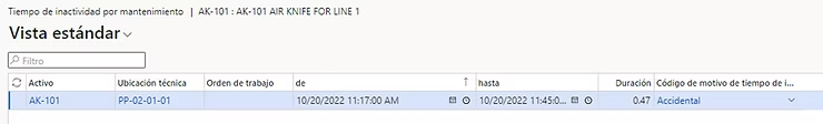
We see how when it does not receive any signal for a configured time it registers a downtime for us so that we can then get the standard Dynamics reports with which the performance of that asset will be measured.
Product Quality
In the next scenario, we will see how to monitor and control the metrics that tell us if the products are within quality thresholds. This scenario allows auditing those measurements that interest us so that we comply with the tolerances configured in D365FO. In this case we are interested in the measurement value, since with it we will see if it meets quality control.
| Element | Function |
|---|---|
| Sensor | Sends a measurement about a particular property of the products. |
| Azure | A record is generated in Redis with the measurement taken. |
| D365FO | Gets data from Redis and checks that it is within the configured threshold. If not, notify the user. |
In the following video you can see how for a time the sensor value is within the acceptable range for that product attribute. At some point the value spikes and Dynamics alerts us so we know that that product is not meeting the stipulated quality. Once the problem is resolved and Dynamics starts receiving correct data, it also alerts us to that so we can assure ourselves that the incident is resolved.
Production Delays
The last scenario allows measuring the actual lifecycle against the planned one to notify delays in production actions. In that scenario, it is necessary for the sensor to send us the number of units being produced (in this case) so we can check if we are within planned times or production is slowing down.
| Element | Function |
|---|---|
| Sensor | Sends a signal with the number of units produced |
| Azure | Metrics: a record is generated for each signal sentNotification: calculates the theoretical quantity per minute and if it’s higher… |
| D365FO | Displays metrics in chartsDisplays the notification |
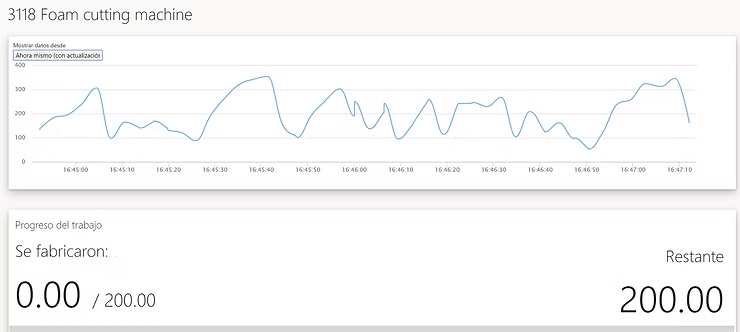
In the following video we can see how the curve that indicates the units produced is losing slope, which indicates that fewer and fewer units are produced per minute. At some point Dynamics recognizes that at this speed we will have a delay in production and alerts us to it.
…and Now What…?
Once we have tested the above examples and see that everything works correctly, we are not going to settle for this standard view but we are going to give it a twist.
Can you imagine that we connected an F1 to D365FO?
Could we see and control the waiting time in a theme park queue?
What if we add an Azure tool to monitor it in real time?
I leave you a preview of the speed chart of an F1 in D365FO and I wait for you in the next article: